Plasma Oxy Software Features
PROProfessional | ALCA-la-Carte | Title |
---|---|---|
Scale and Offset
|
||
Pipe Cutting
|
||
Smart360
|
||
HPR Auto-Gas Control
|
||
Multiple Simultaneous Fabrication Heads
|
||
Customizable Cut Charts
|
||
Advanced Text Tool
|
||
Nest Printing
|
||
Part Numbers
|
||
DXF Export
|
||
Marker and Plasma Marking
|
||
Oxyfuel
|
||
Plasma
|
||
Laser Pointer Hardware and Software
|
||
Laser Pointer
|
||
THC Performance History Chart
|
||
Rip Cut
|
||
Move to Point in Viewport
|
||
Progress Meter
|
||
Kerf Crossing Detection
|
||
Rotary Axis Support
|
||
Workpiece Alignment
|
||
Motor Current Sensing
|
||
Run File Forward and Backwards
|
||
Momentary Run
|
||
Dry Run
|
||
Jump to Line
|
||
Dynamic Ventilation
|
||
Automatic Lead-in on Restart
|
||
Advanced G-Code Management
|
||
Serial Communications for Powermax or HPR
|
||
THC
|
||
Smart Touch Off
|
||
Multiple Tabs
|
||
Collision Avoidance
|
||
Customizable Post Processor
|
||
Advanced Small Hole Processing
|
||
Custom CAM View Modes
|
||
Cutout or Part Mode
|
||
Manipulate Parts in Nest
|
||
Cut Sequencing
|
||
Assign Different Operations per Part
|
||
Animated 3D Cutting Simulation
|
||
Overburn Support
|
||
Advanced Lead-In/-Out Editing
|
||
Part Numbers
|
||
Nesting Report
|
||
Corner Looping
|
||
Grid Nesting
|
||
Advanced True Shape Nesting
|
||
Import and Nest External Parts
|
||
Automatic Kerf Compensation
|
||
True Shape Nesting
|
||
Commonly Used Plate List
|
||
Arc Fitting Tool
|
||
DXF/DWG Import
|
||
Multi Layer Color Import
|
||
Silhouette Image Import
|
||
Centerline Image Import
|
||
Layer Support
|
||
Free Form Stretching and Manipulation
|
||
Part Shading
|
||
Measure Tool
|
||
Shape Welding Tool
|
||
Bridge Entities Tool
|
||
Fix Tool
|
||
Shape Library
|
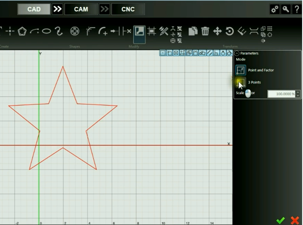
Scale and Offset
Easily scale the size of an entity, or offset and entity to the inside, outside or both.
Easily scale the size or offset the geometry of an entity.
Pipe Cutting
Design, nest and cut round, square and rectangular pipes with ease.
Pipe Cutting includes several tools to enable the easy creation of pipe parts:
- Pipe Shape Wizard creates perfect 3D drawings based on mating pipes of any diameter with a multitude of joints at any angle and any size; including T joints, end caps, miter joints, Y joints and through pipes
- Pipe Sizing Wizard automatically sets OD and thickness of standard pipe sizes
- 3D solid model of pipe joints includes disassembly to preview what both sides of the joint will look like
- Flattened view allows for easy design of custom patterns of any shape; including slots and text
- "Ghost" layout in 2D views show feature wrapping with no interruption
- Pipe True-Shape Nesting enables efficient use of material
Smart360
Smart360™ automatically cuts precision, bolt-quality holes with minimal taper for holes with a diameter to thickness ratio as low as 1:1.
Smart360™ Hole Cutting Technology produces excellent hole quality:
- Auto-recognition of small holes utilizes lower feedrates reducing the internal taper
- Temporarily turns off THC to prevent diving
- Early torch turn-off prevents extraneous marks at the end of hole
- Line-arc lead-in reduces mark at beginning of hole and ensures a uniform feedrate along the entire cutout
- Dynamic kerf compensation enhances the accuracy of each hole
- Can be applied to any small feature—even if it is not a round hole
HPR Auto-Gas Control
Seamless access to all of the HPR controls, gas control, commands and messages, so you can cut precision parts with high definition plasma quickly and easily. Includes Smart360™.
Full system and gas control on HPR 130, 260, 400, 800 Plasma Systems including diagnostics:
- RS-422 connection provides seamless communication between the FlashCut interface and HPR system
- Auto-gas control for mixing the plasma and shield gases
- On-screen control of amperage and pressure
- Separate amperage settings for ramping and full speed cutting
- Seamlessly change from marking to cutting settings on the fly
- Real-time torch status and diagnostics shows status and error messages
- Integrated cut charts for HPR and HSD families
- Precision height control using FlashCut’s Stingray® THC
- Ohmic disconnect circuitry protects system from noise and voltage spikes
- Includes Smart360™ Hole Cutting Technology
Multiple Simultaneous Fabrication Heads
Link multiple oxyfuel or waterjet stations together for simultaneous cutting.
Multiple Simultaneous Fab Heads allows for oxyfuel or waterjet machines to link multiple stations for simultaneous cutting:
- Increase productivity by cutting a part multiple times simultaneously
- Match settings and timing across multiple cutting stations
- Designate a primary station for positioning and process settings
Customizable Cut Charts
Pre-loaded cut charts from the manufacturer with recommended settings such as feedrate, pierce height, cut height and THC set point can be customized.
Standard plasma cut charts can be overridden with custom values using any spreadsheet editing software.
Advanced Text Tool
Short Description
The Advanced Text Tool allows for more powerful manipulation of Text in CAD and CAM:
- Enables text to be fitted to curves—great for signs and other artistic work
- Generates toolpaths in CAM without needing to Explode the object into geometry
Nest Printing
Short Description
The Nest Printing feature (included alongside Part Numbers) can create to-scale printouts and part labels for entire nests:
- Enables printing of hard copies for referencing which parts are included in the nest
- Includes ability to print part name/number labels to any standard label sheet for the use of identifying parts
Part Numbers
Short Description
The Part Numbers feature (included alongside Nest Printing) allows visualization of part names or numbers within a nest in both CAM and CNC modes.
DXF Export
Short Description
Marker and Plasma Marking
Short Description
Oxyfuel
Short Description
Oxyfuel - All of the gas and ignition controls are at your fingertips from preheat to pierce to XY cutting. Precision gas control makes sharp, accurate cuts. Cut charts for leading brands of oxyfuel torches takes the guesswork out of kerfs and feedrates.
Plasma
Short Description
Laser Pointer Hardware and Software
Sleek laser pointer plus software support for using a laser pointer.
Inlcudes laser pointer, mount, cable and software to drive the laser pointer. Great for setting program zero and doing a dry run of a toolpath using the laser pointer instead of cutting with the fabrication head. Distance between laser pointer and fabrication head is automatically compensated for.
Laser Pointer
Software support for using a laser pointer as well as the Workpiece Alignment feature:
- Includes ability for setting Program Zero using a laser pointer
- Enables a 'laser pointer lock' button to run a toolpath with the laser pointer instead of cutting with the fabrication head
- Automatically compensates X/Y distance between laser pointer and cutting head
- Allows skewing the toolpath to match the material's rotation and provides tools to determine the sheet's angle of skew
THC Performance History Chart
A diagnostic tool for height control that displays height data and feedback for the previous ten runs.
Rip Cut
Rip Cut is used to execute simple cuts without making a drawing or writing a G-Code program.
Move to Point in Viewport
Enables the ability to click in the Viewport to designate a specified location to move to while in Move To Point mode.
Move-to-point allows you to move (jog) your tool to a specified exact point simply by CTRL-clicking a destination in the CNC viewport.
Progress Meter
CNC will display a progress bar showing the total estimated time to complete the operation and a countdown of the elapsed time.
Kerf Crossing Detection
Turns off THC while crossing a previous cut on the sheet to prevent unwanted diving.
Rotary Axis Support
Allows the use of and visualization of rotary axes in the CNC Viewport.
Workpiece Alignment
Enables the Program Coordinates to be rotated to accommodate a sheet that is skewed on the machine and conform to the dimensions and orientation of the workpiece.
When using 2-point alignment, the position of the tool is used to define two points on the workpiece that define the angle of rotation. The angle of rotation is calculated by comparing the relative positions of two points selected.
Motor Current Sensing
Allows for a torque-based material sensing option for servo drive systems.
Run File Forward and Backwards
Runs the program forward and, optionally, in reverse.
This is useful when troubleshooting a program in simulation mode or dry run mode. Not typically used while actually cutting. Some commands are not possible to reverse through; For example, M106(fabhead change) and G611(advanced pierce options).
Momentary Run
Dry runs the program in forward or reverse as long as the hollow button is held.
Dry Run
Run a program without cutting.
Jump to Line
This button allows the user to jump or skip ahead to a specific line in the program.
Dynamic Ventilation
Dynamic ventilation systems sense the location of the cutting head, and only activate the ventilation system in the specific zone where it is needed.
The ventilation system is distributed over several zones, each with a damper that can be opened and closed on command.
If your machine is equipped with a dynamic ventilation system, its behavior can be controlled through these settings. For example, by configuring the length of the overlap between adjacent zones, you can ensure that the dampers controlling the airflow to the ventilation system have sufficient time to open and close as the cutting head passes between zones.
Automatic Lead-in on Restart
This option allows for mid-program recovery by cutting an impromptu lead-in whenever the fabrication head is jogged away from the toolpath after a feed hold.
Advanced G-Code Management
Automatically load and run a g-code from a barcode or run a series of g-codes in succession in batch
Advanced file management gives you the ability to automatically load and run a g-code from a barcode or run a series of g-codes in succession in batch mode automatically. Both features are great for streamlining production and minimizing keying errors on the factory floor.
Serial Communications for Powermax or HPR
Enables two-way communication to a variety of plasma models for real-time current, pressure, and gas control as well as error reporting.
THC
FlashCut Integrated StingrayTM THC adjusts Z axis height thousands of times/second.
Maintain a precise distance between the cutting head and your work. Any pattern, any speed, producing smooth edges, sharp details and high precision. Warped stock, bent stock and corrugated sheet stock are handled with ease.
Smart Touch Off
Enables additional features to improve the speed of the Touch Off routine.
Multiple Tabs
Short Description
Automatically applies tabs to hold the part at user-defined intervals or quantities. These can be applied separately to part perimeters and cutouts.
Collision Avoidance
Automatically adjust leads and cut sequence to prevent torch crashes with material.
Increase productivity, reduce cut time and prevent torch crashes by automatically adjusting leads and cut sequence to prevent torch crashes with material.
Customizable Post Processor
Short Description
Customize the FlashCut CNC post processor by adding new lines of G-Code to execute at the beginning and the end of the cut file or in between cuts.
Advanced Small Hole Processing
Automatically reduces feed rate for given small hole size ?
Improve cut quality on small holes through a combination of slowing down the plasma cutting speed and locking the cut height above the material.
Custom CAM View Modes
Short Description
Toggle on and off view modes for kerf width, cut direction, toolpath visibility, and more.
Cutout or Part Mode
Short Description
Select whether the drawing should represent entire parts or simply cutouts. Note that cutouts cannot be nested.
Manipulate Parts in Nest
Short Description
Drag, rotate, copy, and delete individual parts—even after automatically nesting.
Cut Sequencing
Short Description
Apply a manual sequence to toolpaths using this tool. In Part Mode, simply select the order in which the parts should cut. In Operation Mode, select and sequence each cut or mark operation individually.
Assign Different Operations per Part
Short Description
Allows for different tools to apply to the same part such as cutting and marking operations.
Animated 3D Cutting Simulation
Short Description
This simulation creates a preview window to see how the machine will be programmed to run through the nest.
Overburn Support
To ensure a clean cut, you may set the torch to continue through a cut along the same toolpath.
To ensure a clean cut, you may set the torch to continue through a cut along the same toolpath. This feature allows you to determine how far this overburn will go. Lead out lines appear after the overburn
Advanced Lead-In/-Out Editing
Ability to easily edit the strategy or placement of each lead with one simple tool.
The FlashCut CAM software will automatically place lead points in optimal spots with user-defined strategies including the size, angle, geometry, and overburn distance. This feature allows lead-in and lead-out nodes to be easily drag-and-dropped to the ideal position.
Part Numbers
Part Numbers can be displayed on a nest and printed
This feature will tag parts with identification in the software. This comes bundled in a feature suite with Nest Printing functionality in order to easily identify parts after cutting.
Nesting Report
Generates a report from the nested parts, estimating material use, waste, and cost.
Generates a report from the nested parts that estimates material use, waste, and cutting lengths. Material price can be input directly to calculate approximate pricing. All other information is generated automatically from the toolpath.
Corner Looping
Corner looping minimizes dross on sharp, exterior corners
This allows the toolpath to proceed past the corners of each part and returns to the next section part without slowing down. This will use more material but typically produces cleaner corners. The tool contains a parameter to determine what range of angles this will apply to.
Grid Nesting
The grid nesting function duplicates a part in a grid pattern.
The Grid Nesting function duplicates a part in a simple grid pattern. The number of rows and columns is determined by the desired number of parts and the sheet size.
Advanced True Shape Nesting
Nest parts on multiple sheets that are needed for a given nest.
This feature suite improves True Shape Nesting with extra functionality. With Multi-Sheet Nesting, additional sheets can be generated to fit all needed parts within the same job. This allows the operator to load each additional sheet to complete the nest. Fill Sheet will automatically fill the entirety of a single sheet with the specified ratio of parts. Fill-In Part designates a single part to fill the sheet's remnant after the specified number of parts have been nested.
Import and Nest External Parts
Short Description
Bring in DXF or CADCAM files directly to the CAM module to maintain a nest throughout edits to the original files. Note that the original files must be transferred with the nest file if the nest is created away from the machine.
Automatic Kerf Compensation
Short Description
Automatically offset the toolpath from the part's geometry in order to preserve the true size of the part. Approximate kerf widths are taken from plasma cut charts or the configured tool sizes.
True Shape Nesting
Our True Shape Nesting quickly arranges multiple copies of one or more shapes in a manner that minimizes material usage.
The TrueShape nesting function will duplicate, rotate, and translate each part to create a nest that minimizes the amount of material used in a sheet
Commonly Used Plate List
Short Description
FlashCut CAM remembers recently used material and sheet sizes for quick selection.
Arc Fitting Tool
Reduces the number of nodes of a drawing by converting adjacent line segments into arcs.
Greatly simplifies and reduces the size of large artwork drawings by combining many adjacent line segments into arcs within a user given tolerance.
DXF/DWG Import
Imports geometry from DXF and DWG files. This tool can automatically assign marking operations if 'Combine Layers' is selected.
Multi Layer Color Import
This tool creates shapes from the source drawing based on color which can be nested.
This tool creates geometry for a drawing from a source image based on color. Boundaries between different colors define where the lines are drawn. Each new color is placed on a unique layer, which is color-coded and can be nested.
Silhouette Image Import
This tool imports a silhouette image and fits geometry to the outline to instantly create drawings.
Centerline Image Import
Imports a bitmap image and renders each feature as a single toolpath line down the center of the feature.
Imports a bitmap image and renders each feature as a single toolpath line down the center of the feature. Images with defined lines generally result in a cleaner drawing that requires fewer revisions
Layer Support
Easily separate different parts onto different layers. Each layer can be assigned a unique name and color.
Easily separate different parts or part features into layers. Each layer can be assigned a unique name and color.
Free Form Stretching and Manipulation
Any objects or set of objects can be stretched, positioned, or rotated.
Any objects or set of objects in FlashCut CAD can be stretched, positioned, or rotated by manipulating a set of control points with the cursor, or by entering values using the toolbar.
Part Shading
This Part Shading function can be used to easily and quickly determine what features are perimeters and which are cutouts, even in complex drawings.
This function can be used to easily and quickly determine what features are perimeters and which are cutouts, even in complex drawings.
Measure Tool
The tool allows for measurement between any two points.
You can measure entities in one of three modes: as a ruler between points or between entities, or as a protractor between points on an arc. The tool allows for measurement between any two points, and displays offset in X and Y directions.
Shape Welding Tool
Quickly combine multiple shapes into a single shape
Quickly combine multiple shapes into a single shape. The three available operations:
- Weld (combine) solid areas
- Weld Cutouts
- Subtract
Bridge Entities Tool
Connects two or more objects with a bridge that spans the gap between them
Connects two or more objects with a bridge that spans the gap between them. Can also be used to divide a single object into separate objects. The width of each bridge can be set individually
Fix Tool
Easily detects and fixes small breaks or overlaps in any drawing.
This tool will easily detect and fix small breaks or overlaps in any drawing; no matter if it was imported from a DXF file or created directly in FlashCut CAD. Once detected, it will highlight each flaw and enable it to be automatically fixed. This is especially helpful on the tiniest drawing flaws that cannot be seen with the naked eye.
Shape Library
FlashCut CNC offers a library of shapes for both simple and complex parts.
Our Shape Library will allow you to make typical everyday parts like gaskets, flanges, covers, etc. in an instant. Each shape can be tailored to your needs using our simple menus. Any part generated from the Shape Library can be further edited using our drawing tools.