System Grounding
Correct grounding of the system is essential both for safety and proper operation. This document is a general guide on what connections should be made to ensure proper noise mitigation. While this guide is tailored to the demands of plasma cutting systems, the same principles can be applied to any CNC machine.
Grounding Principles
Ground Loops
When multiple ground paths are created, the potential for ground loops exists. These will negatively impact the system’s overall grounding capabilities. As such, ground connections not covered in this guide should be avoided unless explicitly recommended by a FlashCut engineer.
Point-To-Point
Each connection should be made from a single point to another single point and not daisychained. For example, the connection between the star ground and the lifter should be made directly instead of connecting the lifter to the gantry ground point and relying on its connection to the star ground.
Electrical Isolation
When two components are physically connected but electrically isolated, non-conductive hardware must be used. This is especially important when mounting control components in an enclosure that is bonded to the machine.
Wire Gauge
The connection from the plasma to the star ground and from the star ground to the ground rod must follow their specification. If not specified by the plasma manufacturer, use the following chart. If maximum current capabilities of the plasma power supply exceed the listed values, use multiple cables in parallel of the same gauge that sum to the requirement.
| Ground Wire Gauge | |
| AWG Ground Wire Gauge | Max Current (amps) |
| 10 | 30 |
| 8 | 40 |
| 6 | 55 |
| 4 | 70 |
| 3 | 85 |
| 2 | 95 |
| 1 | 110 |
| 1/0 | 125 |
| 2/0 | 145 |
| 3/0 | 165 |
| 4/0 | 195 |
Other connections should use at least 10 AWG unless they exceed 100’. In these cases, use at least 6 AWG instead (safe out to 250’).
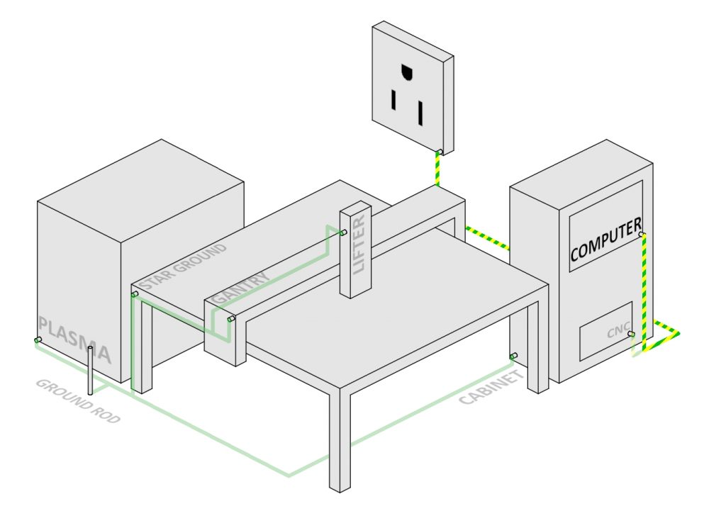
Grounding Overview
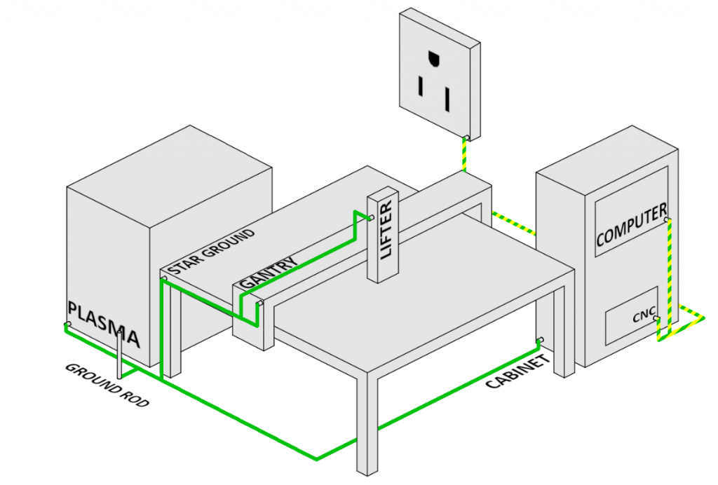
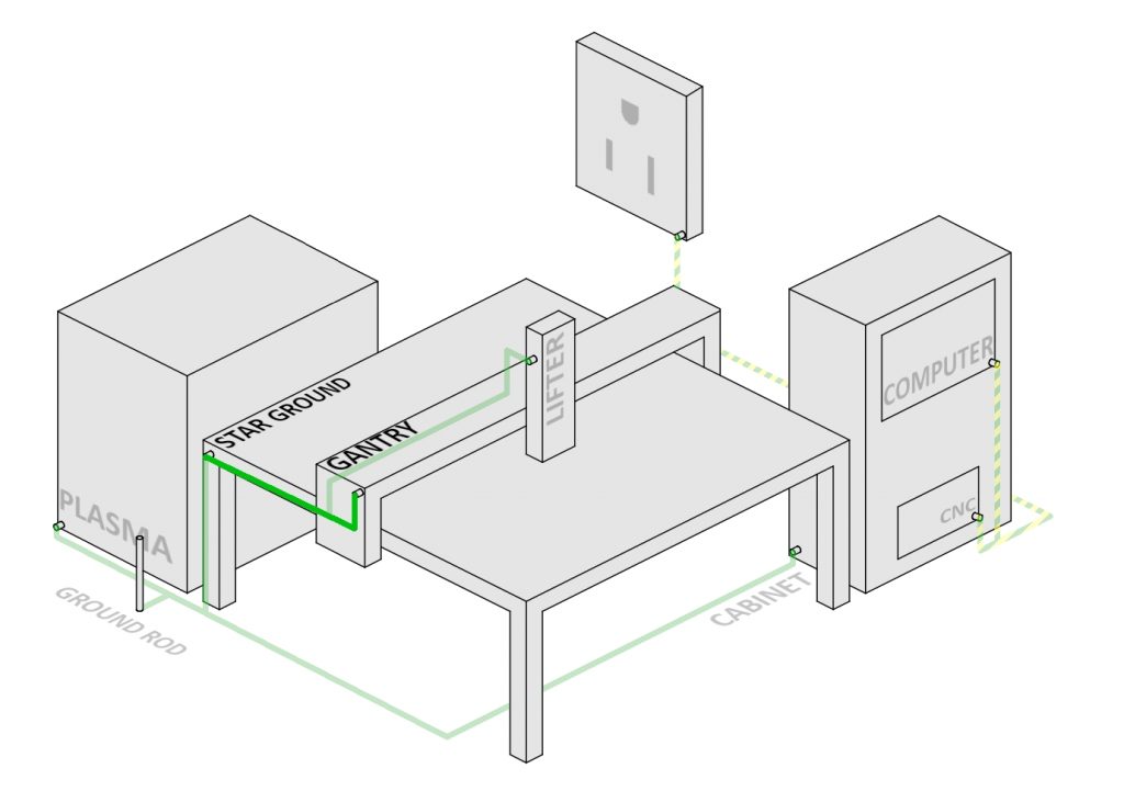
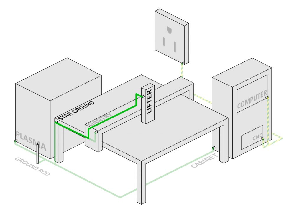
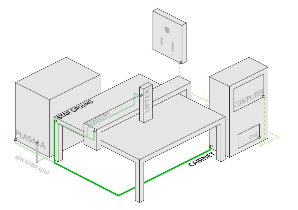
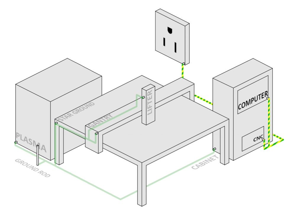
Two separate ground schemes should be used—a machine ground and a control ground. This will protect the more sensitive control electronics from the plasma system. The following diagram shows an example of proper grounding. The two schemes are denoted by the differently patterned wire colors: solid green represents the machine grounding and striped represents control grounding.
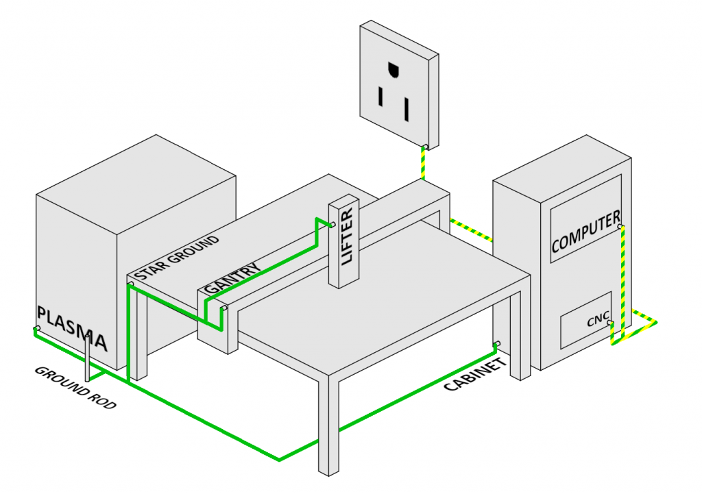
Machine Grounding
Machine grounding encompasses the connections between the table bed, plasma, mechanics, star ground, and ground rod. These are installed to give electrical noise (EMF) induced by the plasma system a path to drain away from more sensitive electronics. Without this system in place, EMF will propagate through other conductive paths to reach ground, potentially striking sensitive equipment such as the control electronics. These connections should be made point-to-point, radiating like branches of a tree. This grounding scheme will prevent ground loops; a common source of EMF. One frequently overlooked cause of ground loops is motor mounting. The shield of motor cables should only be connected at one end, preferably the controller side. 10 AWG or greater should be used for connections between the star ground and machine components.
Ground Rod to Star Ground
The connection from the ground rod to the star ground must conform to the recommendations of the plasma manufacturer. In lieu of manufacturer guidelines, one should follow the recommendations in the Wiring Guidelines section. This connection ensures that any extra energy created by the plasma system has a safe route to follow to ground.
Star Ground to Gantry
A single, uninterrupted connection from the machine’s star ground to the gantry should be made using 6 AWG, at a minimum. This facilitates a path for any noise induced against the structure of the gantry to reach ground cleanly.
Star Ground to Lifter
A single, uninterrupted connection from the star ground to the lifter should be made using 6 AWG, at a minimum. The connection can not be daisy-chained; this prevents a single failure from affecting the entire system. This facilitates a part of a healthy machine grounding scheme by allowing noise induced by the plasma torch a path to earth ground.
Star Ground to Cabinet
A ground connection from the star ground to the control cabinet is only recommended if the control cabinet is bonded to the machine via welds or conductive hardware. If the control cabinet is completely electrically isolated from the rest of the machine (if it is free-standing, for example), it is a good practice to instead connect it to the control ground scheme.
Control Grounding
Control grounding entails the ground connection between computer, controller, monitor, and any other low-power devices. Often times, this will be accomplished through the devices’ AC cables. If only DC power is supplied to the computer or controller, an external ground wire should be run to the power supply. The control grounding scheme must be separate from the machine grounding scheme. Following recommended practices will keep control grounds electrically isolated from machine grounds and prevent ground loops. To verify this, a resistance measurement can be taken from the chassis of any of these devices to the frame of the table. This value should read in kilo-Ohms or greater.
Computer Grounding
The computer chassis should be isolated from the machine ground. It should also be grounded to the electrical panel. This is usually done through the AC plug. If the control enclosure has been tied to the machine grounding scheme, the computer must be electrically isolated using non-conductive materials such as plastic hardware. This also includes peripherals such as a monitor, keyboard, or USB hub.
CNC Controller Grounding
The CNC controller chassis should be isolated from the machine ground. It should also be grounded to the electrical panel. This is usually done through the AC plug. If the control enclosure has been tied to the machine grounding scheme, the controller, like the computer, must be electrically isolated using non-conductive materials such as plastic hardware.
Cable Routing
Another potential source for electrical noise-related problems is cable routing. Care should be taken to isolate cables connected to the control system from cables connected to the machine system as much as is possible. In particular, long, parallel runs of both types of cables should be avoided. One of the most common errors is running the CNC plasma control cable alongside the plasma lead. While visually clean, the proximity of the cables allows for noise to easily transmit from the machine system into the control system.
Piles and coils of cable may also have a deleterious effect on the electrical health of the machine. If cable runs are longer than necessary, a “figure-eight” should be used instead of a straight coil