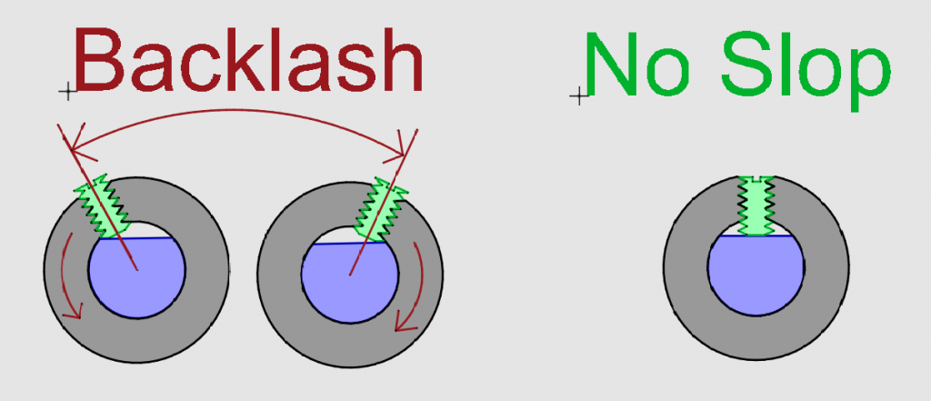
What is Backlash?
Mechanical backlash refers to the looseness or play in a system that causes lost motion. If this goes unnoticed in your CNC machine, it can result in inaccurate parts with unwanted flat spots or holes that are far from round.
The 5 main factors that can contribute to backlash in mechanical systems are:
- Manufacturing tolerances: Inherent tolerances in the manufacturing process can lead to slight variations in the size and shape of components or gear teeth, creating gaps between them.
- Wear and tear: Over time, the teeth of a gear, rack, or pinion can wear down, increasing the clearance between them and exacerbating the backlash problem.
- Temperature fluctuations: Changes in temperature can cause the metal components of the system to expand and contract, which can affect the meshing of the teeth and increase backlash.
- Improper alignment: Misalignment between meshing mechanical components can lead to uneven contact between the teeth, creating additional gaps and increasing backlash.
- Loose components: Over time components can come loose which causes mechanical slop and inherently greater backlash. It is important to make sure all mounting and set screws are tight and secure to minimize mechanical slop.
By understanding the causes and effects of mechanical backlash and implementing appropriate mitigation strategies, engineers can design and maintain rack and pinion systems that deliver high levels of precision and performance.
What does Backlash Look Like?
If you ever see flat spots or inaccurate parts in your CNC-cut parts, it can be a cause of mechanical backlash.
Oftentimes, you might erroneously think that this is a motion control issue in the software or motors. However, the flat spots are a tell-tale sign of backlash.
Important to know: In the case of backlash, this inaccuracy in parts is very consistent and repeatable.
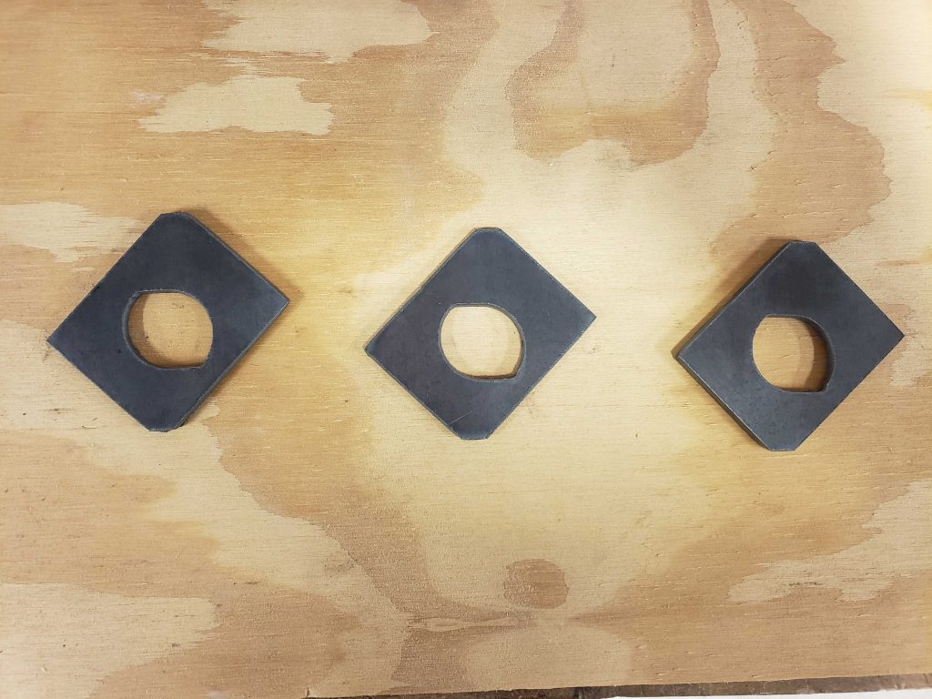
Let us show you some examples of parts cut on machines with backlash.
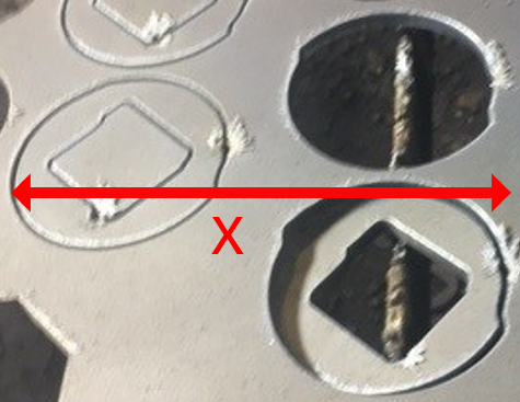
In this first example, both the discs and diamonds have flat spots on the left and right. These flat spots were caused by excessive backlash in the X-axis. When this axis changed direction, there was a delay in actual axis movement while it was moving through the backlash gap. During that whole time, the Y-axis stayed in motion – which is what causes the flat spots along the Y-axis.
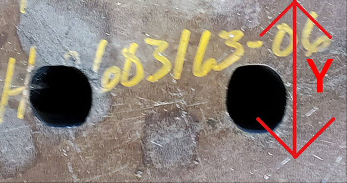
Similarly, the flat spots on the top and bottom of the holes below were caused by excessive play in the Y-axis mechanics.
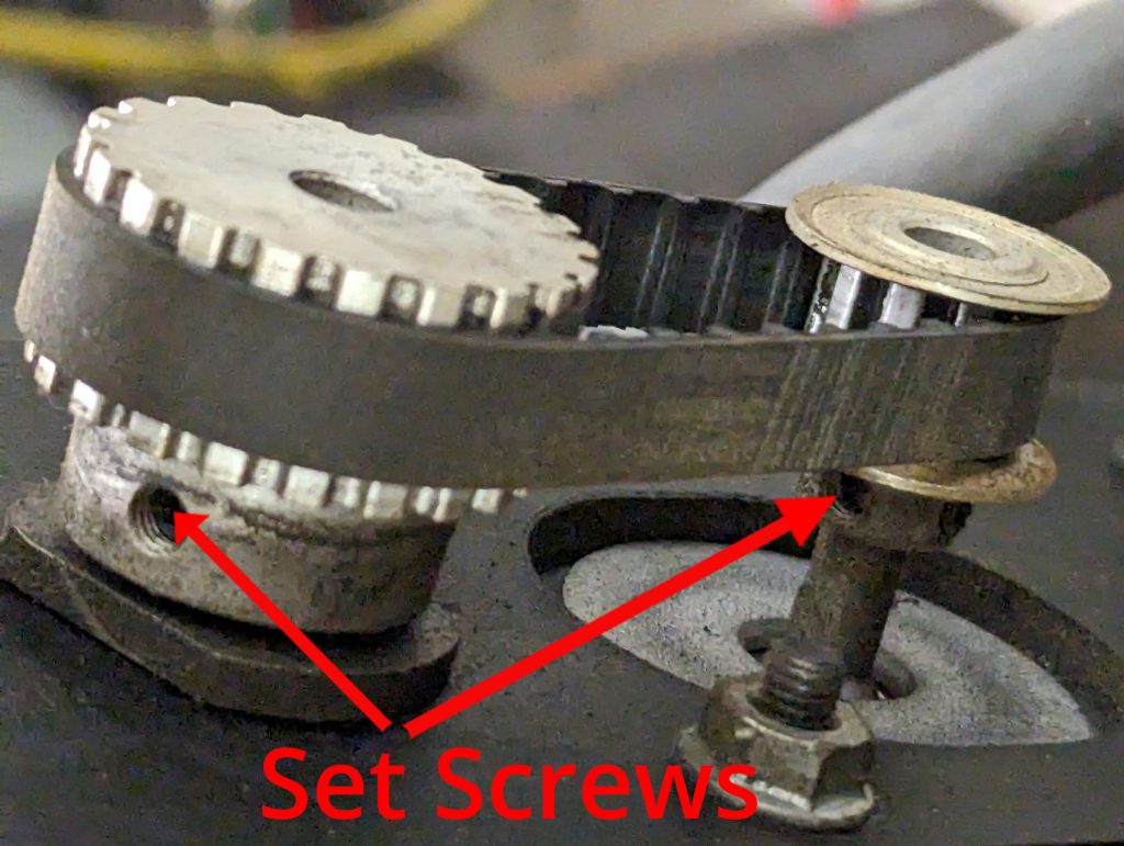
The picture below shows the same part before and after (top and bottom, respectively) correcting the mechanical backlash caused by loose set screws on the pinion gear.
Types of Backlash
There are many types of mechanical backlash. Here are the 5 most common ones we see in CNC machines:
- In a rack and pinion system: Too much play or clearance in the meshing
- In a gear train: Too much play or clearance in the meshing
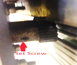
- On a pulley, pinion, or gear: Loose set screws
- In a leadscrew-driven system: Excessive wear on a screw or nut
- In a belt-driven system: Loose timing belt
Rack and Pinion Backlash
In a rack and pinion system, backlash is caused by an excessive gap between the teeth of the rack and pinion gear.
This gap allows the pinion to rotate slightly without engaging the rack, resulting in lost motion and reduced positional accuracy.
To reduce backlash for a no-slop system, you should adjust the pinion gear location to the distance between the rack and pinion.
Some systems employ a spring-loaded gear to eliminate the backlash, but caution should be taken as it can cause gear interference and unwanted backloads on a servo system.

Note: Good quality components with tight manufacturing tolerances will also minimize backlash.
Gear Train Backlash
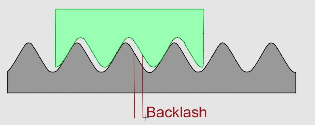
The diagram below illustrates a gear pair with mechanical backlash. As the drive (blue) gear goes clockwise, it engages the driven (grey) gear. The gap between the teeth represents the backlash you get as the gears change their rotation direction.
When the drive gear reverses its motion, there is a momentary gap before the teeth of the driven gear fully engage in the opposite direction. This gap is the reason behind the lost motion or play associated with mechanical backlash.
Note: This truly highlights its impact on precision and responsiveness in mechanical systems.
Tightening the distance between these gears will eliminate backlash for a no-slop system and enhance the performance of mechanical systems.

Important to know: Gearboxes typically have a series of meshing gears in them which contribute to an overall backlash value for the gearbox. In general, better-quality gearboxes will have lower overall backlash but will be more expensive.
Loose Component Backlash
Another common source of backlash is loose components. If there is a gear or pulley attached to a motor or the end of a gearbox with a loose set screw, then angular backlash will occur every time you switch directions.
This amount of backlash can be relatively large.
For example, if there is a loose set screw between the flat of the motor shaft (blue) and the hub (gray) of a 2” or 25mm pitch diameter pinion which amounts to 20 degrees of slop, then the system would lose about 10mm (≈ 0.39”) every time it switched directions – which is very significant.
(Total Slop = Backlash Angle/360 x Pitch Dia x Pi)
Because of this, it is imperative that all set screws are tight and secured with Loctite. It is also good practice to have two set screws on larger-diameter shafts.
Backlash From Loose Timing Belts
In a belt drive system, if a belt or a set of screws on any pulleys is loose, it can also exhibit backlash.
Ensure the best performance by making sure the belt has no slop in it.
To do this, tighten the distance between the drive pulley and the driven pulley or add an idler gear to take up the slack.
Leadscrew (Worm Gear) Backlash
There is also an inherent backlash in an ACME leadscrew (grey) and nut (green) assembly. This can be reduced with an anti-backlash spring-loaded nut or with a ball screw assembly.
Measuring Backlash
You can use the FlashCut CNC software to help identify the amount of backlash in the drive mechanics of an axis using the following steps:
- Jog the axis in the negative direction – enough so that you overcome any backlash in that direction.
- Use Move to Point mode to travel 1” in the opposite direction. The “Move to Point” mode can be accessed through the top left button on the job panel.

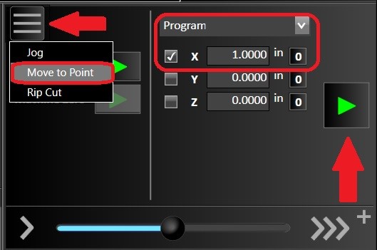
Note: Only the axis you intend to move should have the checkbox selected. In the example below, we are testing the X-axis.
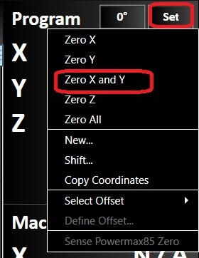
- Create a mark under the fabrication head’s position or some easily referenced point on the machine. Set the axes coordinates to zero with the ‘Set’ dropdown in the Program Coordinate panel.

- Once again, travel 1” in the same direction to return to the axis’s zero. The DRO for that Axis should be zero. If the fabrication head does not return to the original mark, this will indicate the presence of backlash in that axis.
- You can use a caliper to determine this amount, or you can incrementally jog in the same direction until you are aligned with the original mark. At this point, the DRO value will be the amount of backlash that you have.
Backlash Compensation
If you are unable to remove the mechanical backlash, you can use backlash compensation software. This will correct the toolpath, but there will be some dwell every time the machine corrects the backlash.
For a plasma process, this would be unacceptable. For a milling or router process, this could leave a tool mark which may or may not be acceptable.
To use the software backlash compensation:
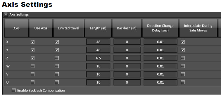
- Go to the Axis Settings panel in the configuration
- Set the measured amount of backlash for each axis.
Note: If you do not want to use backlash compensation, set this to Zero.